A few of the engineering tools built into Stinger Pro — free to use, right here. Inside the program, these run on the same screen where you bid the job: tied to your takeoff, with save, print, and a dozen more.
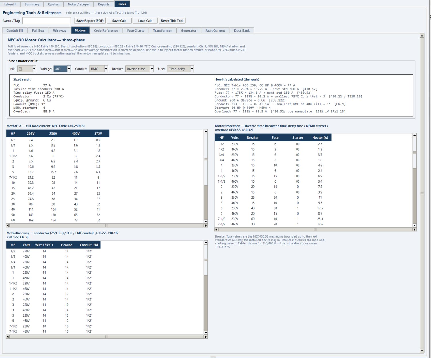
Motor Calculator — NEC Article 430 (3-phase)
Full-load current from Table 430.250, with branch conductor, protection, and grounding.
FLC per NEC Table 430.250 (3-phase induction). Branch conductor at 125% FLC (430.22) from the 75°C copper column; maximum inverse-time-breaker protection at 250% FLC (430.52); EGC per 250.122. Verify motor nameplate and design type.
Code Reference
NEC quick reference — the same tables built into Stinger Pro. Scroll to find what you need. For estimating reference only; verify against the current NEC and your AHJ.
Feeder Tap Rules
10-Foot Tap Rule [240.21(B)(1)]
Tap conductor ampacity ≥ 1/10 of the OCPD rating protecting the feeder; tap ≤ 10 ft; terminates in a single OCPD ≤ tap ampacity; does not extend beyond the enclosure.
25-Foot Tap Rule [240.21(B)(2)]
Tap conductor ampacity ≥ 1/3 of the feeder OCPD rating; tap ≤ 25 ft; terminates in a single OCPD ≤ tap ampacity; protected from physical damage.
Conductor Fill Adjustment — NEC 310.15(B)(3)(a)
Current-Carrying Conductors
% of Ampacity
4 – 6
80%
7 – 9
70%
10 – 20
50%
21 – 30
45%
31 – 40
40%
41 or Above
35%
Standard OCPD Ampere Ratings — NEC 240.6(A)
Through 800 A — the 28 standard breaker/fuse sizes:
The Ampere Interrupting Capacity is the largest fault current a single overcurrent device — a breaker or fuse — can safely open without being damaged. Per NEC 110.9, every device must have an interrupting rating at least equal to the available fault current at the point where it is installed.
SCCR — short-circuit current rating (an assembly)
The Short-Circuit Current Rating is the largest fault current a complete assembly — a panelboard, switchboard, or piece of equipment — can withstand for the time the protective device takes to clear, without becoming a hazard (NEC 110.10). It is a property of the labeled assembly, not of one device inside it.
Rule of thumb
AIC is per-device interrupting ability; SCCR is per-assembly withstand ability. Both must meet or exceed the available fault current. On a bid, AIC/SCCR is usually a spec callout that prints on the report and may not narrow the catalog — but it must be recorded.
Allowable ampacity, 60/75/90°C, not more than 3 current-carrying conductors in raceway.
Size
Cu 60°C
Cu 75°C
Cu 90°C
Al 60°C
Al 75°C
Al 90°C
14
15
20
25
—
—
—
12
20
25
30
15
20
25
10
30
35
40
25
30
35
8
40
50
55
30
40
45
6
55
65
75
40
50
55
4
70
85
95
55
65
75
3
85
100
115
65
75
85
2
95
115
130
75
90
100
1
110
130
145
85
100
115
1/0
125
150
170
100
120
135
2/0
145
175
195
115
135
150
3/0
165
200
225
130
155
175
4/0
195
230
260
150
180
205
250
215
255
290
170
205
230
300
240
285
320
195
230
260
350
260
310
350
210
250
280
400
280
335
380
225
270
305
500
320
380
430
260
310
350
600
350
420
475
285
340
385
700
385
460
520
315
375
425
750
400
475
535
320
385
435
800
410
490
555
330
395
445
900
435
520
585
355
425
480
1000
455
545
615
375
445
500
Conductor Properties — NEC Table 8
Class B stranded; DC resistance @ 75°C, ohms per 1000 ft.
Size
Strands
O.D. (in.)
Area (in.²)
CU ohm/kFT
CU-coated ohm/kFT
AL ohm/kFT
14
7
0.073
0.004
3.14
3.26
5.17
12
7
0.092
0.006
1.98
2.05
3.25
10
7
0.116
0.011
1.24
1.29
2.04
8
7
0.146
0.017
0.778
0.809
1.28
6
7
0.184
0.027
0.491
0.51
0.808
4
7
0.232
0.042
0.308
0.321
0.508
3
7
0.26
0.053
0.245
0.254
0.403
2
7
0.292
0.067
0.194
0.201
0.319
1
19
0.332
0.087
0.154
0.16
0.253
1/0
19
0.372
0.109
0.122
0.127
0.201
2/0
19
0.418
0.137
0.0967
0.101
0.159
3/0
19
0.47
0.173
0.0766
0.0797
0.126
4/0
19
0.528
0.219
0.0608
0.0626
0.1
250
37
0.575
0.26
0.0515
0.0535
0.0847
300
37
0.63
0.312
0.0429
0.0446
0.0707
350
37
0.681
0.364
0.0367
0.0382
0.0605
400
37
0.728
0.416
0.0321
0.0331
0.0529
500
37
0.813
0.519
0.0258
0.0265
0.0424
600
61
0.893
0.626
0.0214
0.0223
0.0353
700
61
0.964
0.73
0.0184
0.0189
0.0303
750
61
0.998
0.782
0.0171
0.0176
0.0282
800
61
1.03
0.834
0.0161
0.0166
0.0265
900
61
1.094
0.94
0.0143
0.0147
0.0235
1000
61
1.152
1.042
0.0129
0.0132
0.0212
1250
91
1.289
1.305
0.0103
0.0106
0.0169
1500
91
1.412
1.566
0.00858
0.00883
0.0141
1750
127
1.526
1.829
0.00735
0.00756
0.0121
2000
127
1.632
2.092
0.00643
0.00662
0.0106
AC Resistance & Reactance — NEC Table 9
600V, 3-phase, 60 Hz, 75°C; ohms to neutral per 1000 ft. XL = reactance; R = AC resistance; Ze = effective impedance @ 0.85 PF; columns by conduit (PVC / Aluminum / Steel).
Size
XL PVC/Al
XL Steel
R Cu PVC
R Cu Al
R Cu Stl
R Al PVC
R Al Al
R Al Stl
Ze Cu PVC
Ze Cu Al
Ze Cu Stl
Ze Al PVC
Ze Al Al
Ze Al Stl
14
0.058
0.073
3.1
3.1
3.1
—
—
—
2.7
2.7
2.7
—
—
—
12
0.054
0.068
2.0
2.0
2.0
3.2
3.2
3.2
1.7
1.7
1.7
2.8
2.8
2.8
10
0.05
0.063
1.2
1.2
1.2
2.0
2.0
2.0
1.1
1.1
1.1
1.8
1.8
1.8
8
0.052
0.065
0.78
0.78
0.78
1.3
1.3
1.3
0.69
0.69
0.7
1.1
1.1
1.1
6
0.051
0.064
0.49
0.49
0.49
0.81
0.81
0.81
0.44
0.45
0.45
0.71
0.72
0.72
4
0.048
0.06
0.31
0.31
0.31
0.51
0.51
0.51
0.29
0.29
0.3
0.46
0.46
0.46
3
0.047
0.059
0.25
0.25
0.25
0.4
0.41
0.4
0.23
0.24
0.24
0.37
0.37
0.37
2
0.045
0.057
0.19
0.2
0.2
0.32
0.32
0.32
0.19
0.19
0.2
0.3
0.3
0.3
1
0.046
0.057
0.15
0.16
0.16
0.25
0.26
0.25
0.16
0.16
0.16
0.24
0.24
0.25
1/0
0.044
0.055
0.12
0.13
0.12
0.2
0.21
0.2
0.13
0.13
0.13
0.19
0.2
0.2
2/0
0.043
0.054
0.1
0.1
0.1
0.16
0.16
0.16
0.11
0.11
0.11
0.16
0.16
0.16
3/0
0.042
0.052
0.077
0.082
0.079
0.13
0.13
0.13
0.088
0.092
0.094
0.13
0.13
0.14
4/0
0.041
0.051
0.062
0.067
0.063
0.1
0.11
0.1
0.074
0.078
0.08
0.11
0.11
0.11
250
0.041
0.052
0.052
0.057
0.054
0.085
0.09
0.086
0.066
0.07
0.073
0.094
0.098
0.1
300
0.041
0.051
0.044
0.049
0.045
0.071
0.076
0.072
0.059
0.063
0.065
0.082
0.086
0.088
350
0.04
0.05
0.038
0.043
0.039
0.061
0.066
0.063
0.053
0.058
0.06
0.073
0.077
0.08
400
0.04
0.049
0.033
0.038
0.035
0.054
0.059
0.055
0.049
0.053
0.056
0.066
0.071
0.073
500
0.039
0.048
0.027
0.032
0.029
0.043
0.048
0.045
0.043
0.048
0.05
0.057
0.061
0.064
600
0.039
0.048
0.023
0.028
0.025
0.036
0.041
0.038
0.04
0.044
0.047
0.051
0.055
0.058
750
0.038
0.048
0.019
0.024
0.021
0.029
0.034
0.031
0.036
0.04
0.043
0.045
0.049
0.052
1000
0.037
0.046
0.015
0.019
0.018
0.023
0.027
0.025
0.032
0.036
0.04
0.039
0.042
0.046
NEMA Enclosure Types
Type
Use
Protects against
1
Indoor
Contact with live parts; falling dirt.
2
Indoor
Type 1 plus dripping and light splashing water.
3
Indoor/Outdoor
Windblown dust; rain, sleet, snow; external ice.
3R
Indoor/Outdoor
Falling dirt; rain, sleet, snow; external ice (no windblown dust).
3S
Indoor/Outdoor
Like Type 3; external mechanisms operable when ice-laden.
3X
Indoor/Outdoor
Type 3 plus added corrosion resistance.
3RX
Indoor/Outdoor
Type 3R plus added corrosion resistance.
3SX
Indoor/Outdoor
Type 3S plus added corrosion resistance.
4
Indoor/Outdoor
Windblown dust; rain/snow; splashing and hose-directed water; ice.
4X
Indoor/Outdoor
Type 4 plus corrosion resistance (stainless / nonmetallic).
Circulating dust, lint, fibers; dripping/light splashing (no knockouts).
12K
Indoor
Type 12 but with knockouts.
13
Indoor
Dust; spraying water; oil and non-corrosive coolant.
7
Indoor (hazardous)
Class I, Div 1, Groups A-D — explosive gas atmospheres.
8
Indoor/Outdoor (hazardous)
Class I, Div 1 — oil-immersed equipment.
9
Indoor (hazardous)
Class II, Div 1, Groups E-G — combustible dust.
10
Mining (MSHA)
Meets MSHA 30 CFR Part 18.
Diesel Locomotive (DLO) Cable — RHH/RHW-2, 2 kV
DLO (Diesel Locomotive) cable is a heavy-duty flexible power cable: Class I rope-lay tinned-copper conductor, EPDM (thermoset) insulation, and a chlorinated-polyethylene (CPE) jacket. Southwire's HDFPC-DLO is listed RHH/RHW-2 for 2 kV in sizes 14 AWG through 1111 kcmil (UL 44). Max continuous operating temp is 90°C wet or dry, 130°C emergency/overload, 250°C short-circuit; rated to -40°C cold-bend (CSA C22.2 No. 38). It is oil, heat, flame, abrasion, and sunlight resistant. Sizes 1/0 AWG and larger are rated for cable-tray use.
Ampacity in raceway
Size
NEC 75°C
DLO 75°C
NEC 90°C
DLO 90°C
Conduit Ø
12
25
28
30
32
2"
10
35
37
40
42
2"
8
50
51
55
57
3"
6
65
67
75
76
3"
4
85
87
95
99
3"
3
100
101
115
115
3"
2
115
116
130
131
3"
1
130
134
145
151
3"
1/0
150
153
170
173
3"
2/0
175
176
195
198
3"
3/0
200
201
225
227
3"
4/0
230
232
260
261
3"
250
255
267
290
301
4"
262
261*
274
297*
309
4"
313
292*
303
327*
342
4"
350
310
325
350
366
4"
444
355*
371
400*
419
4"
500
380
396
430
448
4"
535
394*
409
444*
463
4"
646
438*
469
491*
530
5"
750
475
513
535
581
5"
777
483*
517
545*
585
5"
800
490
530
555
606
5"
900
520
562
585
637
5"
929
527*
565
593*
641
5"
1000
545
605
615
686
6"
1111
564*
641
637*
728
6"
Ampacity in free air
Size
NEC 75°C
NEC 90°C
DLO 75°C
DLO 90°C
12
35
40
46
52
10
50
55
60
68
8
70
80
80
90
6
95
105
106
120
4
125
140
140
157
3
145
165
161
182
2
170
190
186
210
1
195
220
216
244
1/0
230
260
250
281
2/0
265
300
288
325
3/0
310
350
334
376
4/0
360
405
387
436
250
405
455
430
485
262
417*
468*
439
496
313
468*
527*
498
562
350
505
570
532
600
444
577*
651*
621
701
500
620
700
663
749
535
643*
725*
681
770
646
716*
808*
766
867
750
785
885
843
954
777
801*
903*
853
966
800
815
920
874
990
900
870
980
933
1058
929
888*
1001*
950
1078
1000
935
1055
986
1119
1111
992*
1119*
1028
1167
Minimum bend radius
Cable Overall Diameter (O.D.)
Min. Bend Radius
O.D. ≤ 1 inch
4 × D
1.001 in ≤ O.D. ≤ 2 inches
5 × D
O.D. > 2 inches
6 × D
* = value interpolated from the NEC 310.15(B)(16)/(17) table. Conduit diameters in the raceway table are oversized to avoid duct-fill and jam-ratio issues. Bend radius: D = cable overall diameter. Lugs/connectors: use fine-stranded-rated lugs (ILSCO, Burndy, Thomas & Betts) made for DLO / welding / Type W / Type G cable. Print legend: "SOUTHWIRE <size> AWG (mm2) EPR/CPE 2KV HDFPC-DLO TYPE RHH OR RHW-2 (-40°C) ... RW90 EP 2KV ... FT4 ... MSHA".
For estimating and reference only. These calculators are provided as a convenience and demonstration. They do not replace engineering judgment. Always verify against the current adopted edition of the NEC (NFPA 70), manufacturer data, and your local authority having jurisdiction (AHJ) before designing or installing.
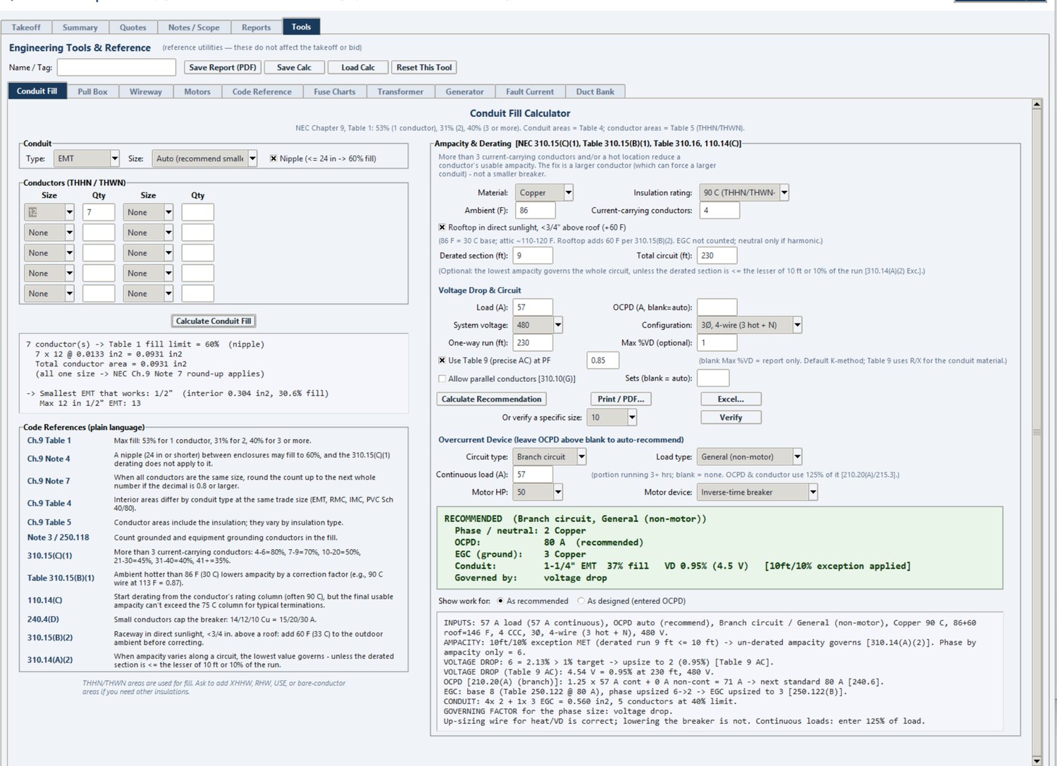
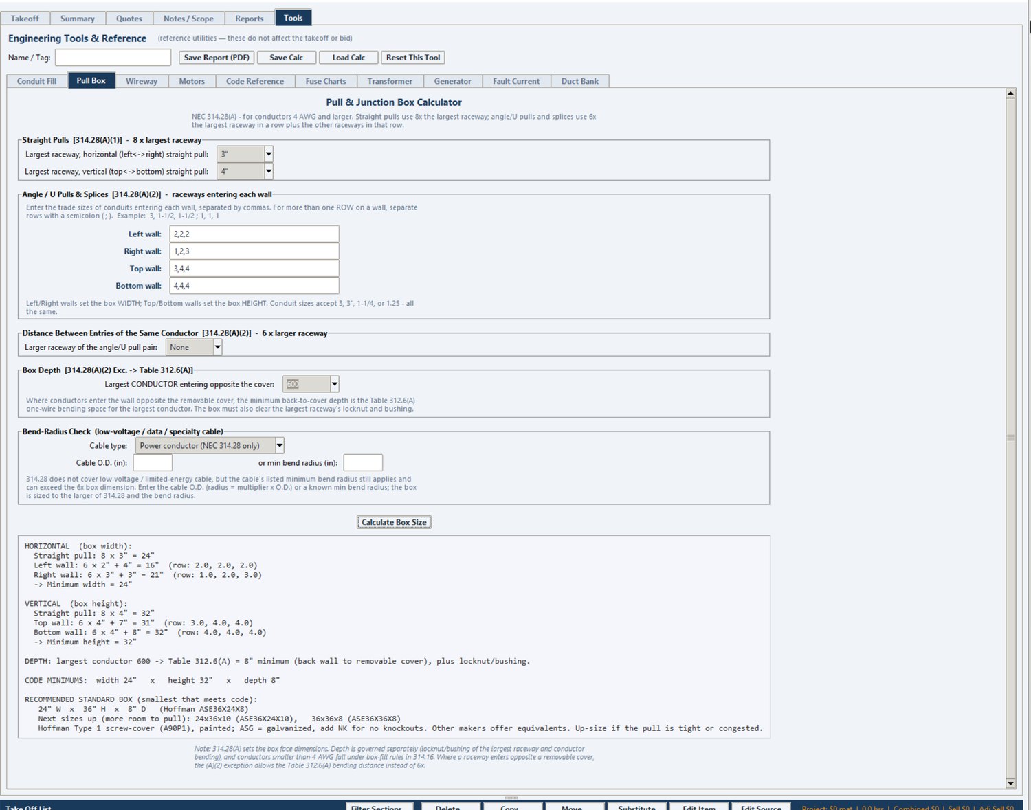
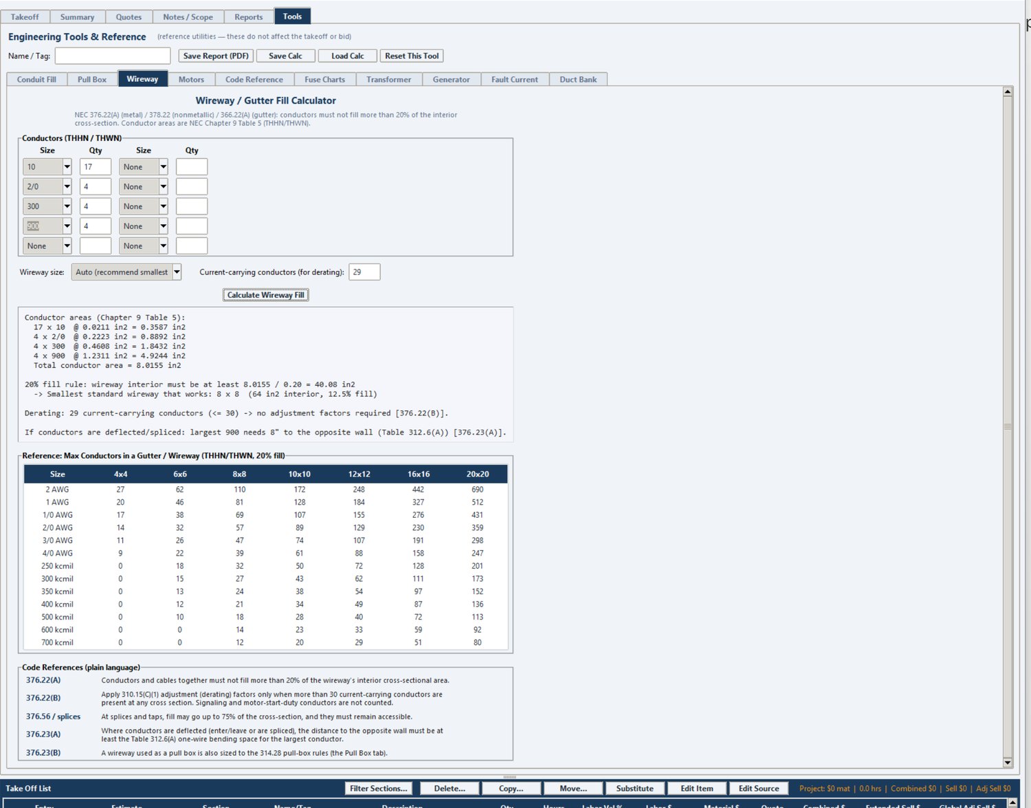
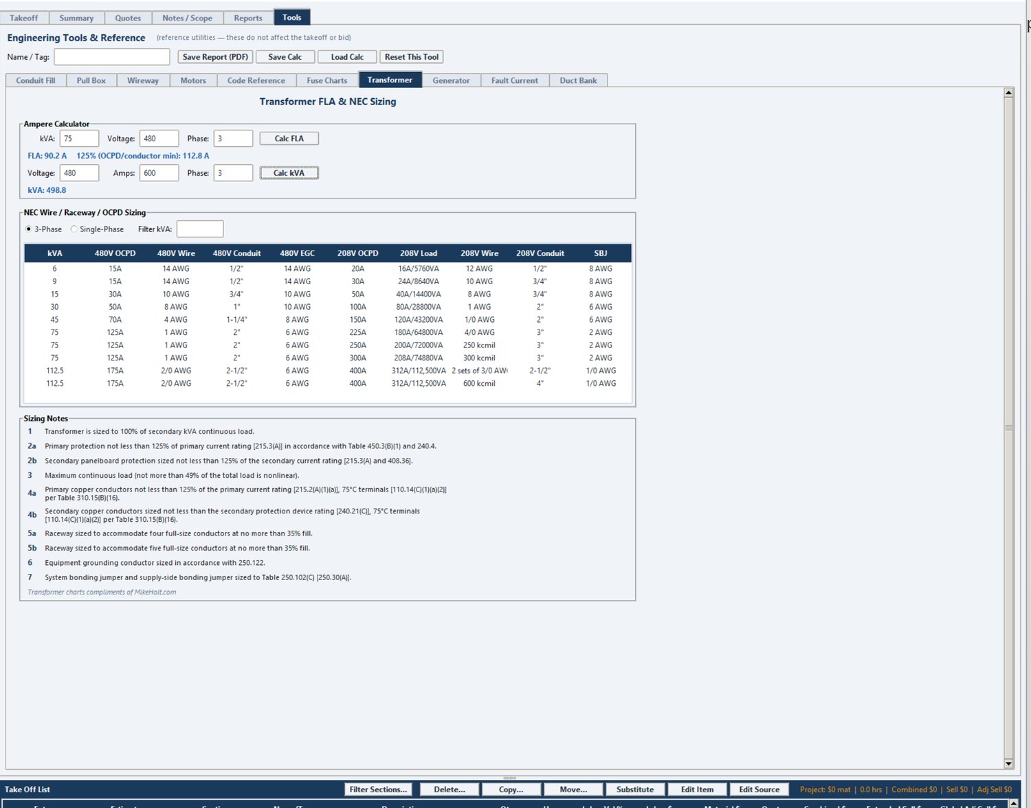
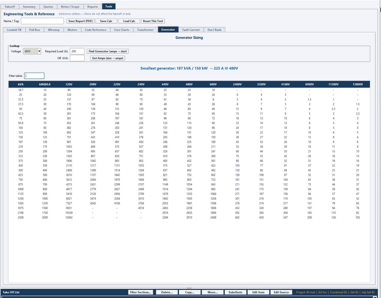
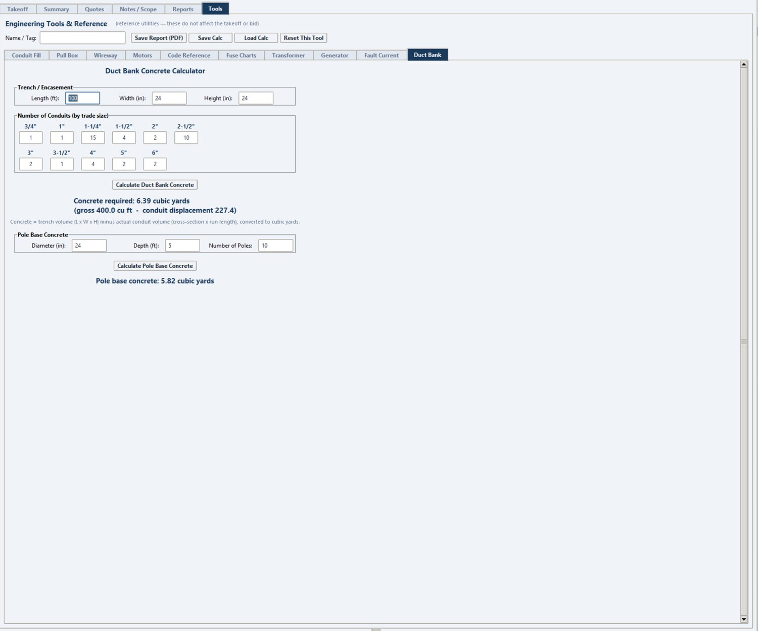
The motor calculator and code reference are a sample of the tools built into Stinger Pro. Conduit fill, voltage drop, pull box, wireway, duct bank, transformer and generator sizing, and fuse charts all run inside your estimate — tied to the takeoff, with save and print.
Inside the program
The same tools, with the full in-program view.
Live calculators above give you the idea — but inside Stinger Pro each tool shows its full work, reference tables, and code citations, on the same screen where you price the job. A look at the real thing:
NEC 430 Motor CalculatorConduit Fill & AmpacityPull & Junction BoxWireway / Gutter FillTransformer FLA & SizingGenerator SizingDuct Bank Concrete
Early access
Want all of it in one program?
These calculators, your takeoff, your estimate, your schedule, and your books — in one place.