Enter the fire pump and jockey pump motors, the supply and the conductor run. The app sizes the overcurrent device to carry locked-rotor current, sizes the conductors, checks starting and running voltage drop against 695.7, lists what must not be in the circuit and writes a PDF.
The app’s own example, every screen in order, 11 steps.
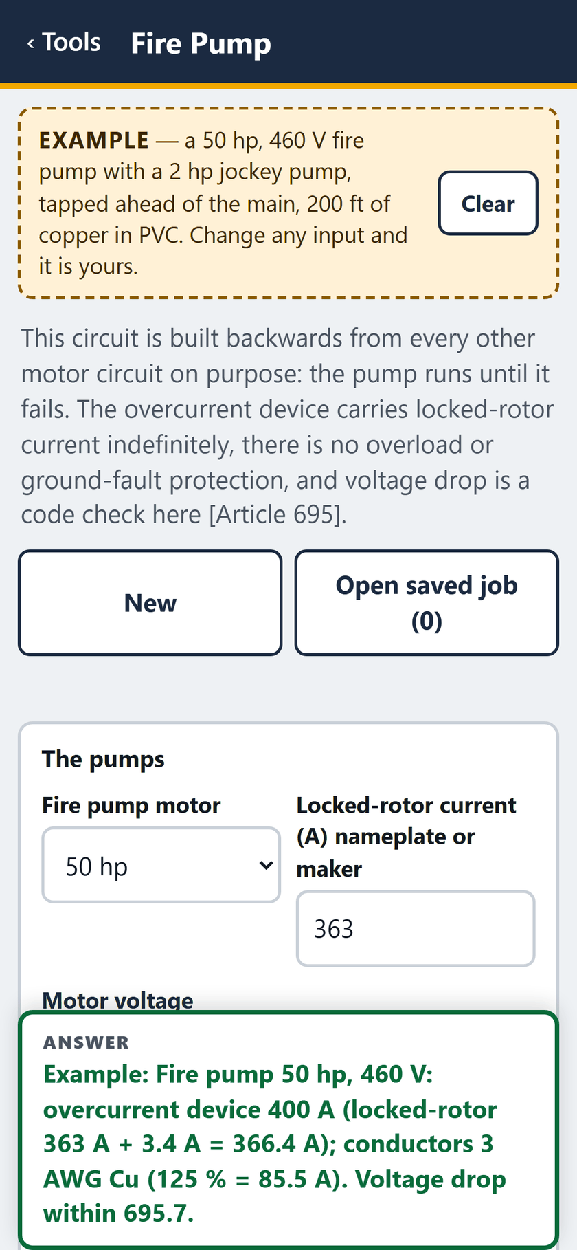
STEP 1 OF 11The example opens filled in: a 50 hp, 460 V fire pump with a 2 hp jockey pump, tapped ahead of the main, 200 ft of copper in PVC.
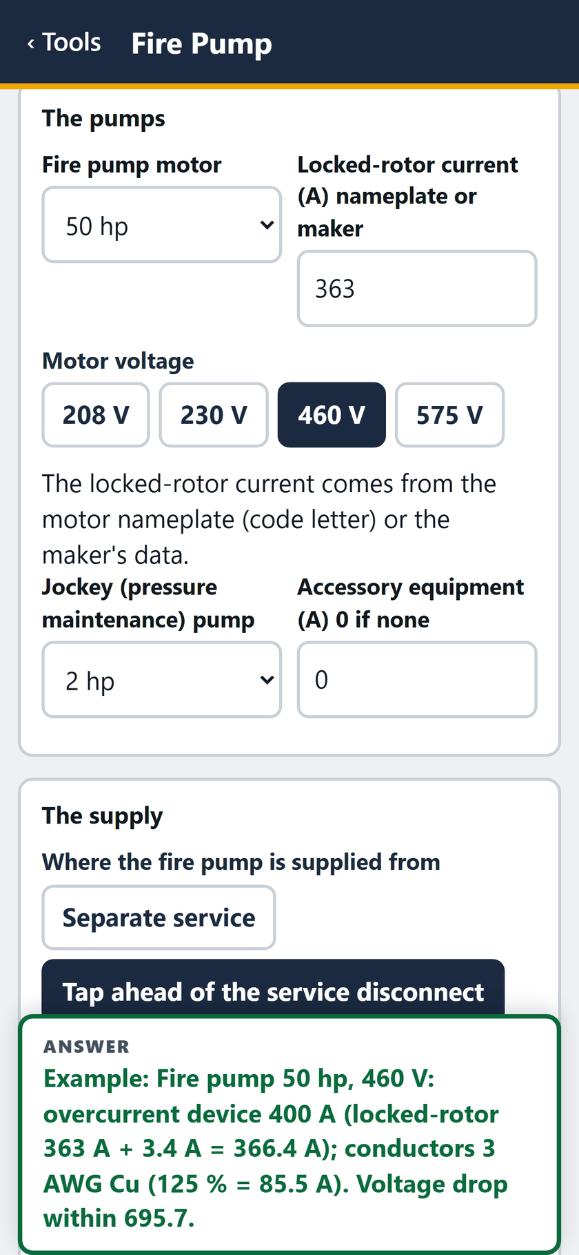
STEP 2 OF 11The pumps: 50 hp, locked-rotor 363 A, 460 V, a 2 hp jockey pump, no accessory load. Supplied by a tap ahead of the service disconnect.
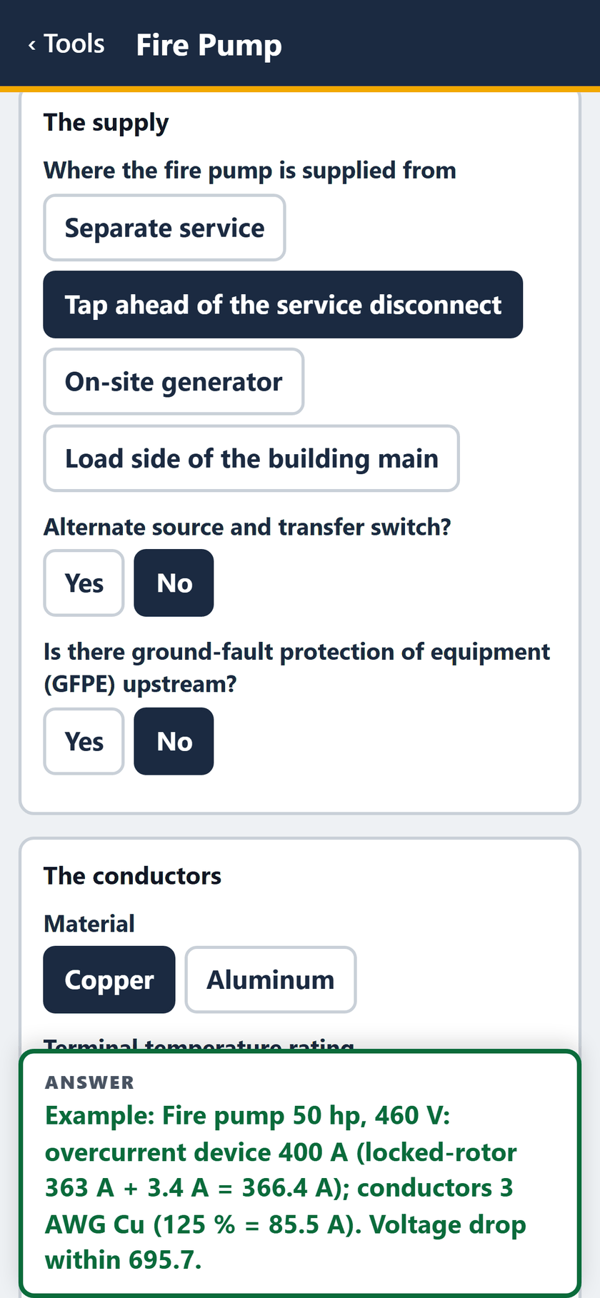
STEP 3 OF 11The supply: tapped ahead of the service disconnect, no alternate source, no GFPE upstream. The conductors are copper.
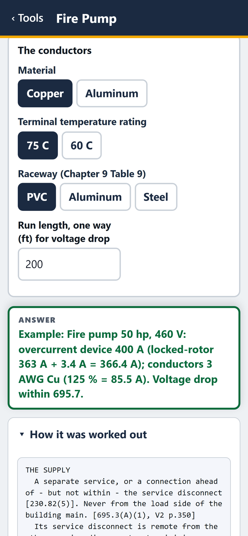
STEP 4 OF 1175 C terminals, PVC raceway, 200 ft one way. The answer: 400 A device, 3 AWG Cu, voltage drop within 695.7.
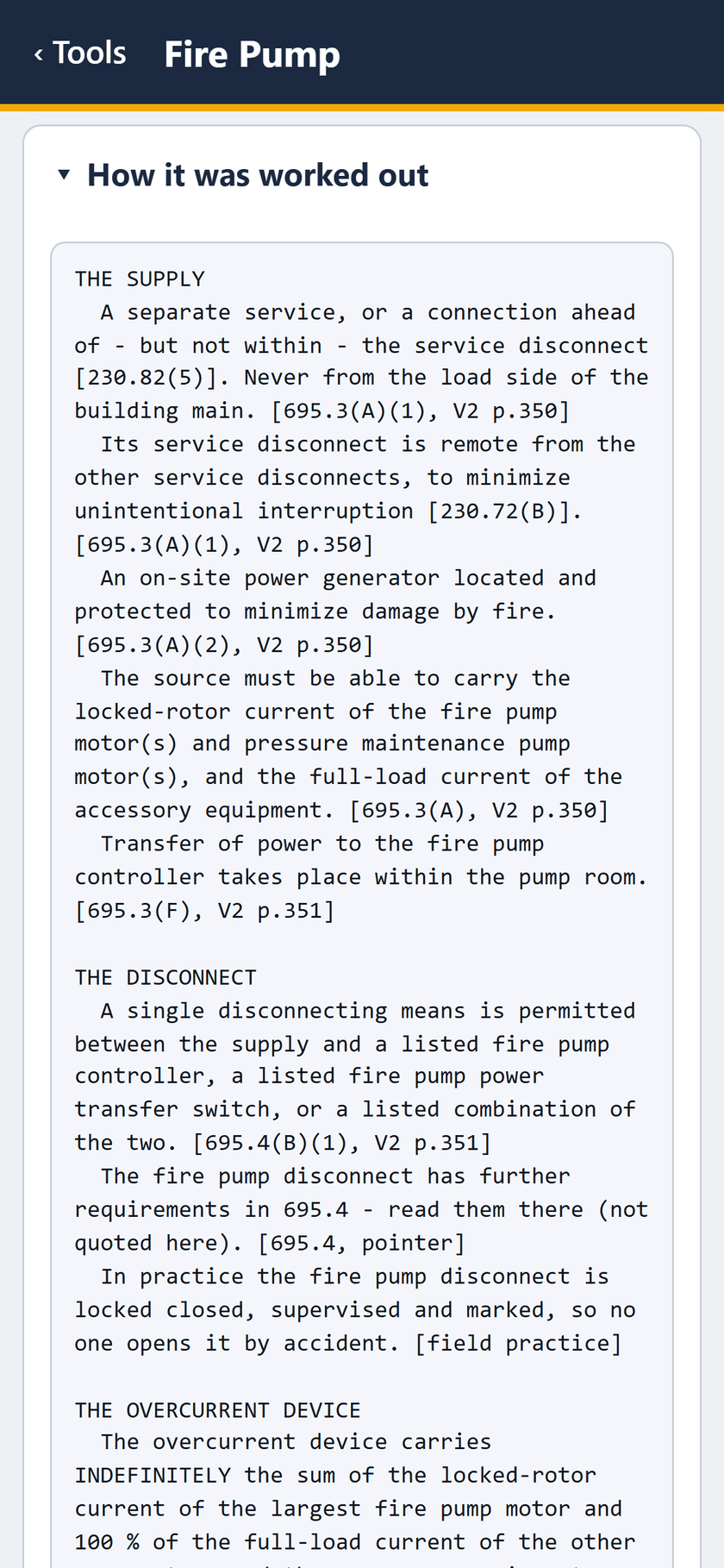
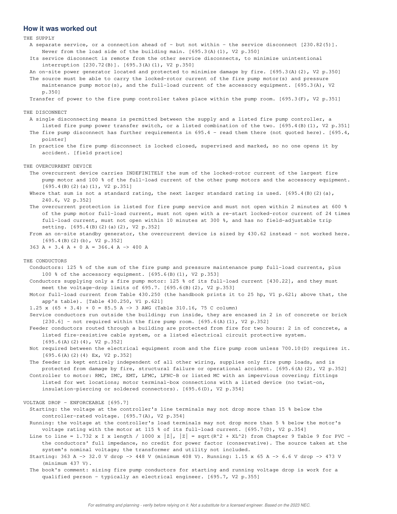
STEP 5 OF 11How it was worked out: the supply and the disconnect, each with its 695 section.
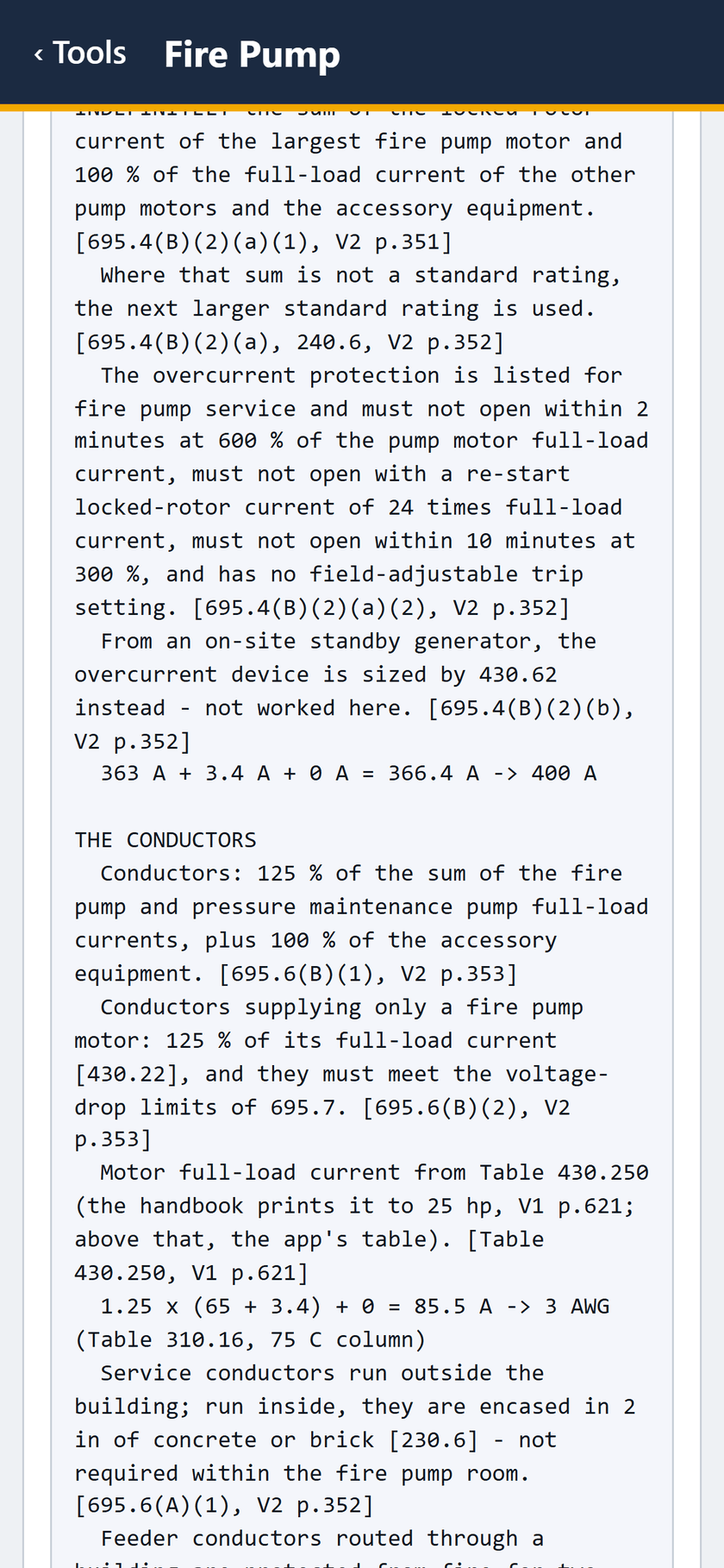
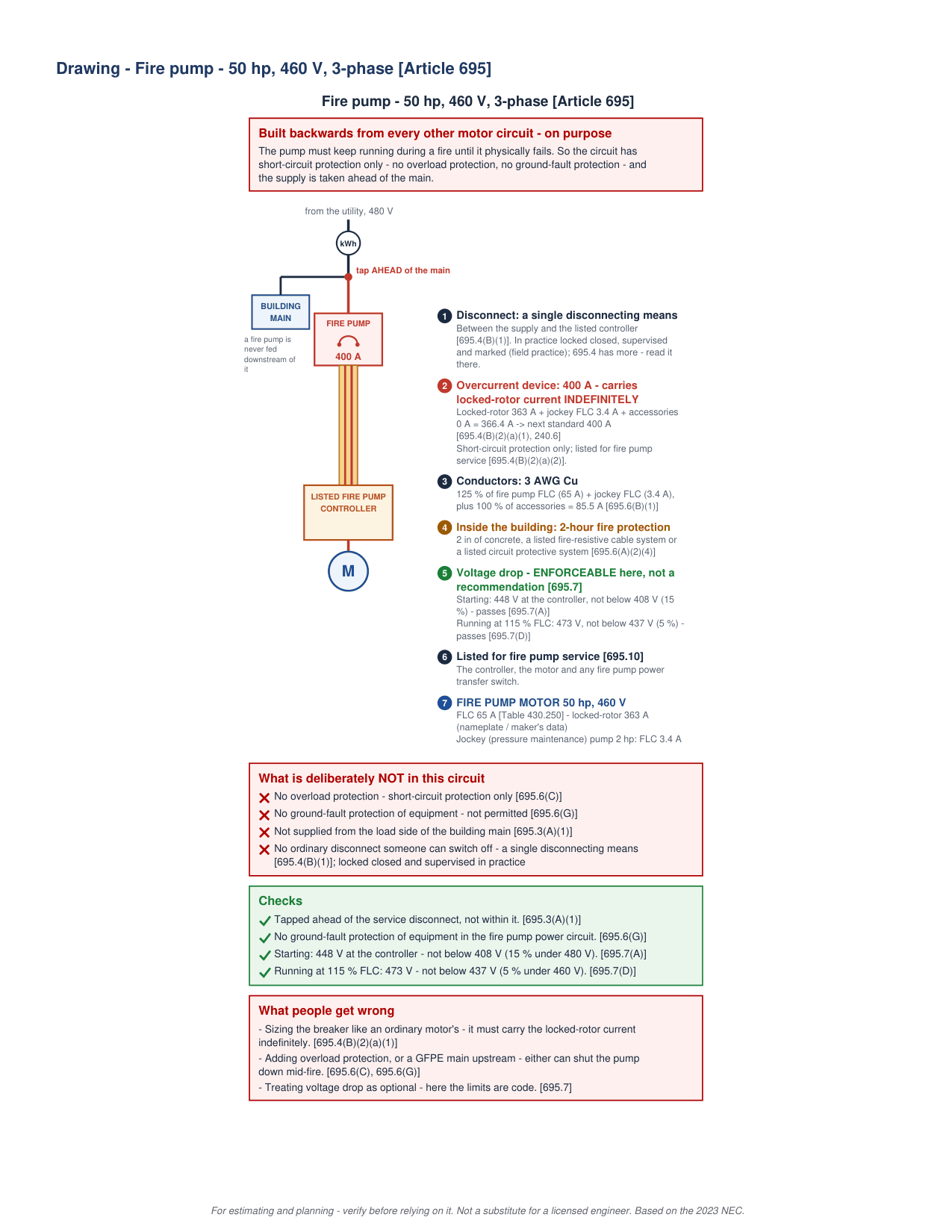
STEP 6 OF 11The overcurrent device: 363 A + 3.4 A + 0 A = 366.4 A, to 400 A. The conductors: 1.25 x (65 + 3.4) = 85.5 A, 3 AWG.
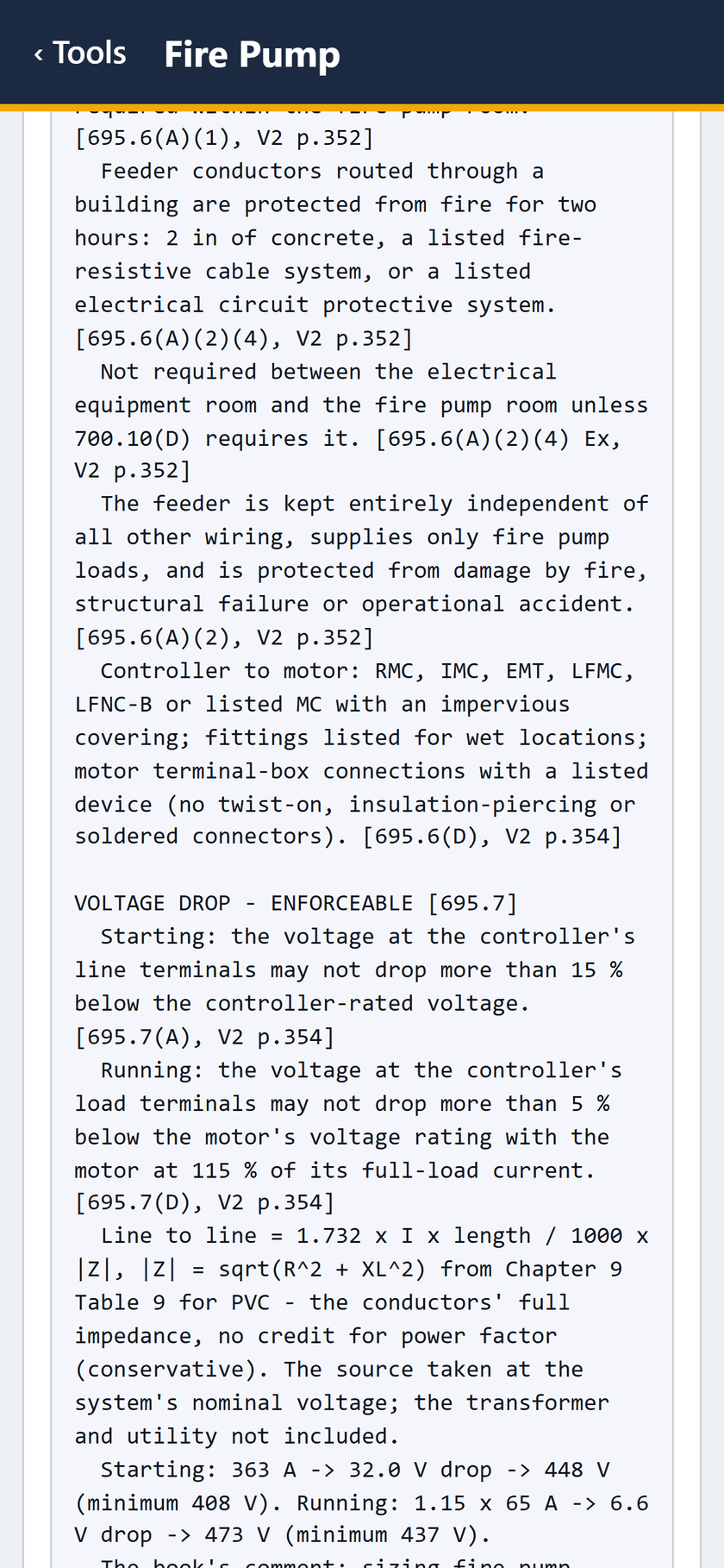
STEP 7 OF 11Feeder fire protection for two hours, the controller-to-motor wiring, then voltage drop under 695.7: starting 448 V, minimum 408 V.
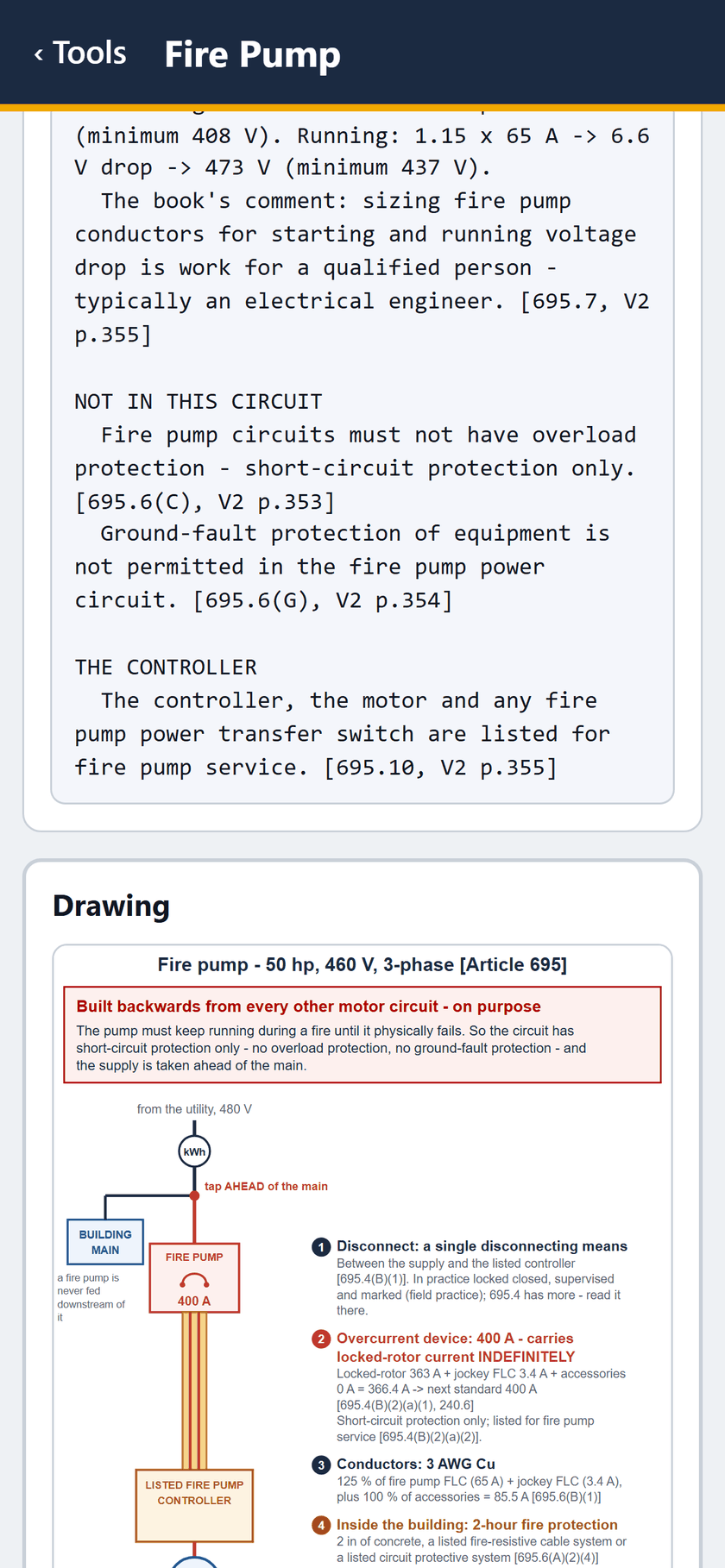
STEP 8 OF 11Running: 473 V, minimum 437 V. Not in this circuit: overload and ground-fault protection. Then the controller, and the drawing begins.
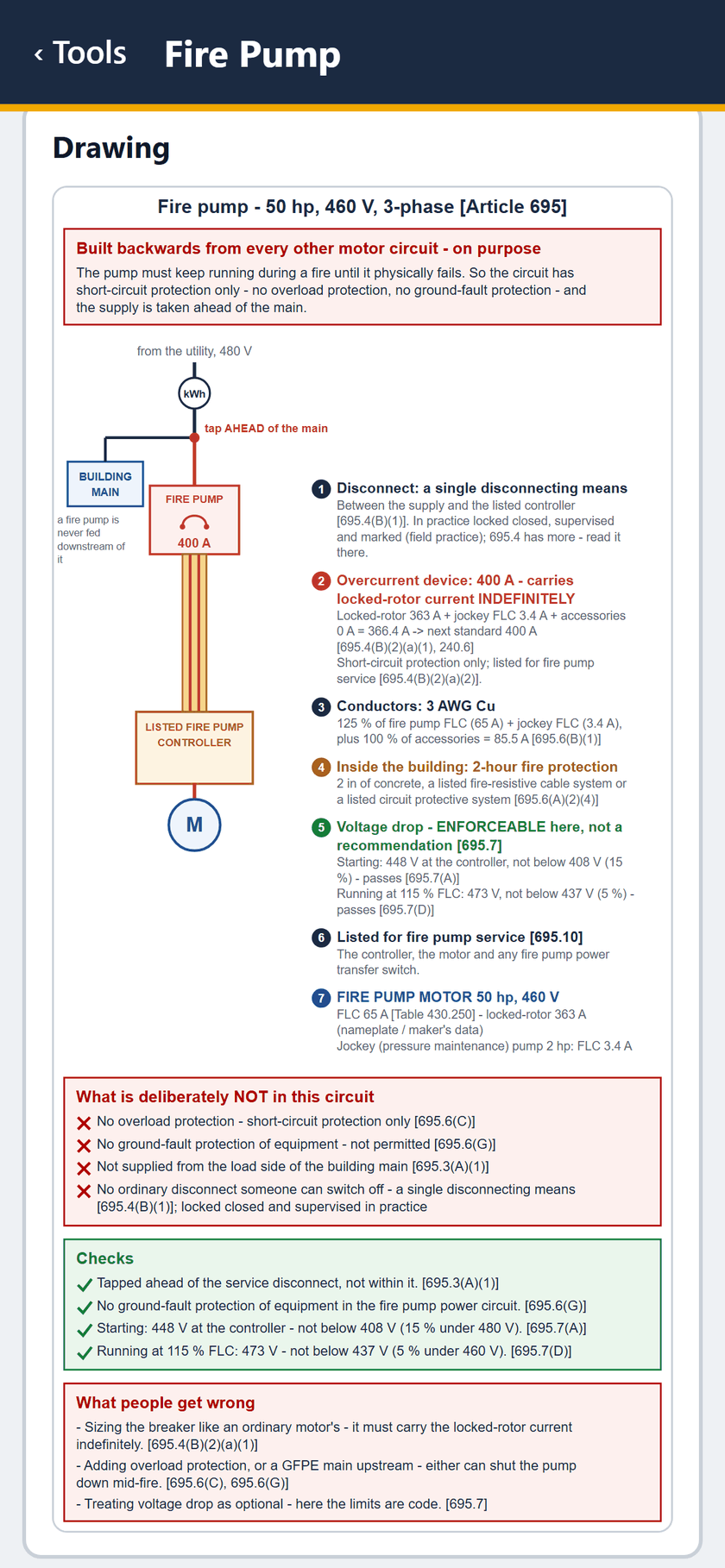
STEP 9 OF 11The drawing: tap ahead of the main, 400 A device, controller and motor, seven numbered notes, the checks and what people get wrong.
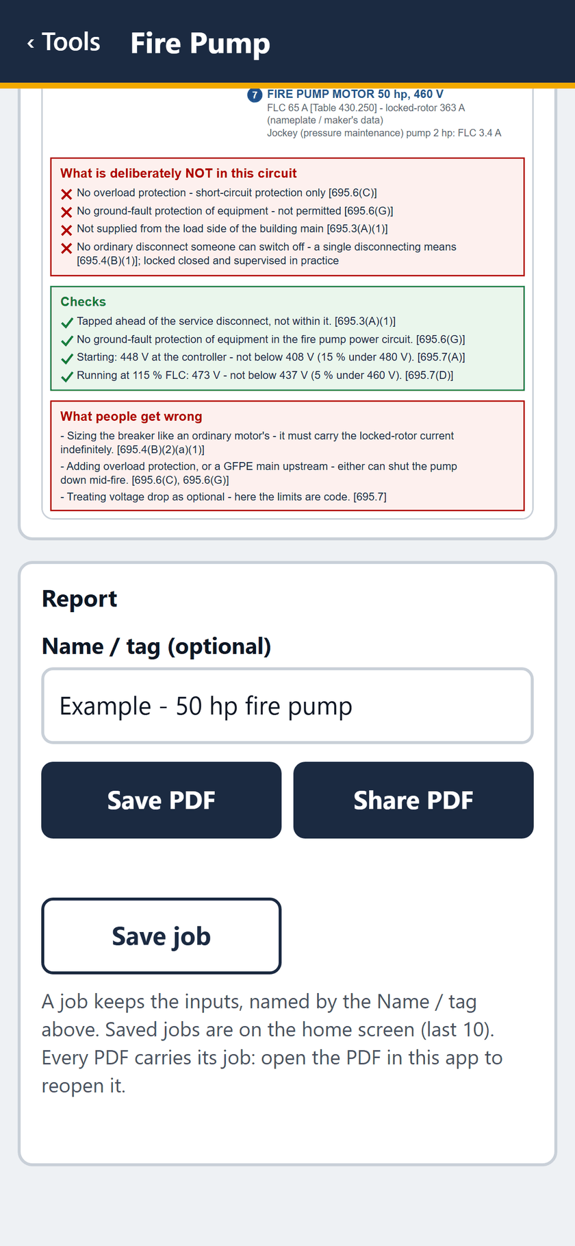
STEP 10 OF 11The end of the drawing, then the report: save or share the PDF, or save the job.
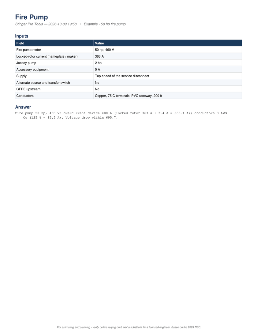
STEP 11 OF 11The PDF, page 1: the inputs and the answer, a 400 A device and 3 AWG Cu, voltage drop within 695.7.
The same 11 screens with the captions burned in. No sound.
MP4, 1.7 MB, 12 seconds.
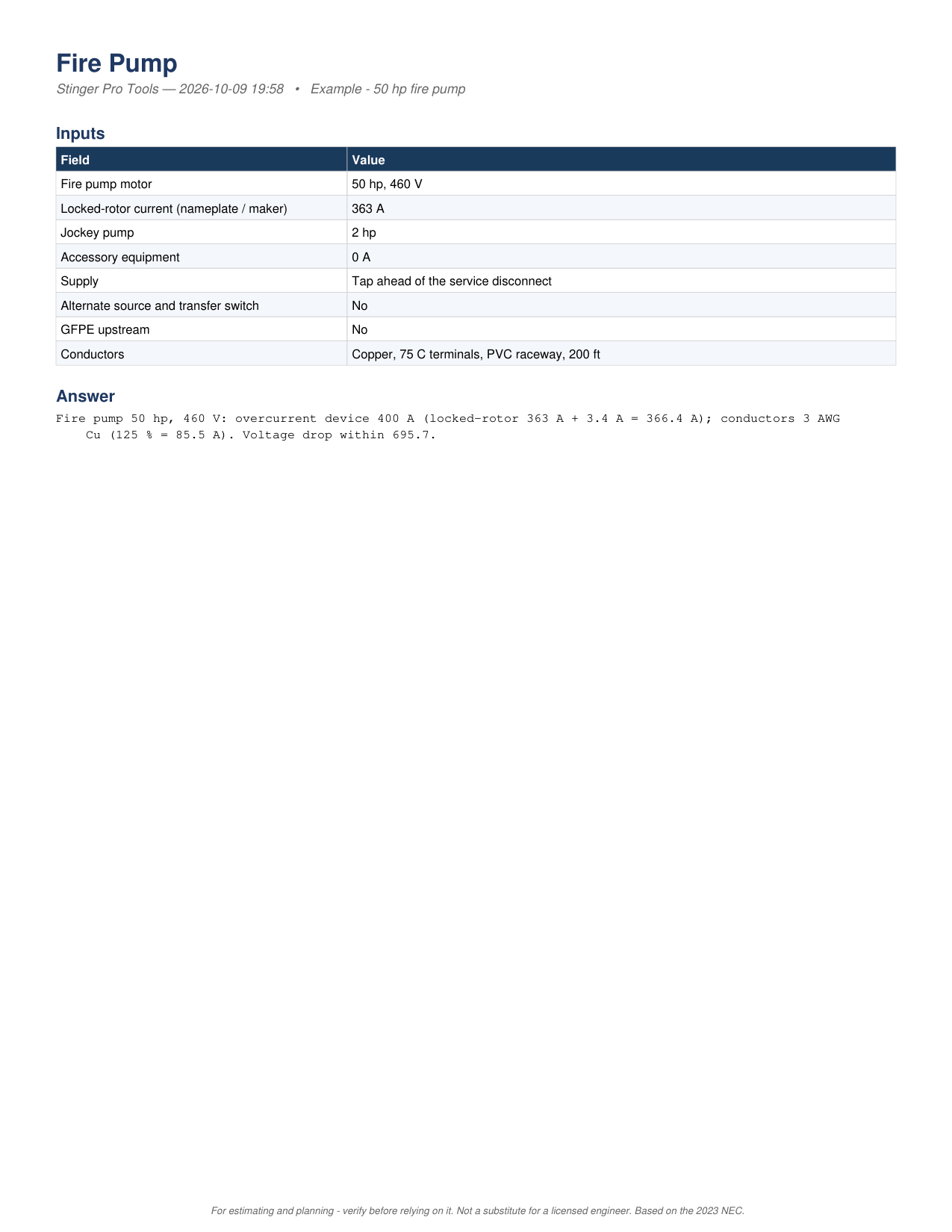
The PDF report for the same job, all 4 pages as the app writes it.
On Android, $49.99 once. Everything on this page.

Fire Pump is not in the Suite. It was built for the app and runs only in Stinger Pro Tools.