The tool takes the transformer, the utility’s fault figure and up to three runs of conductor. It gives the available fault current at the service, the switchboard and the branch circuit, 3-phase and L-N, with every formula shown.
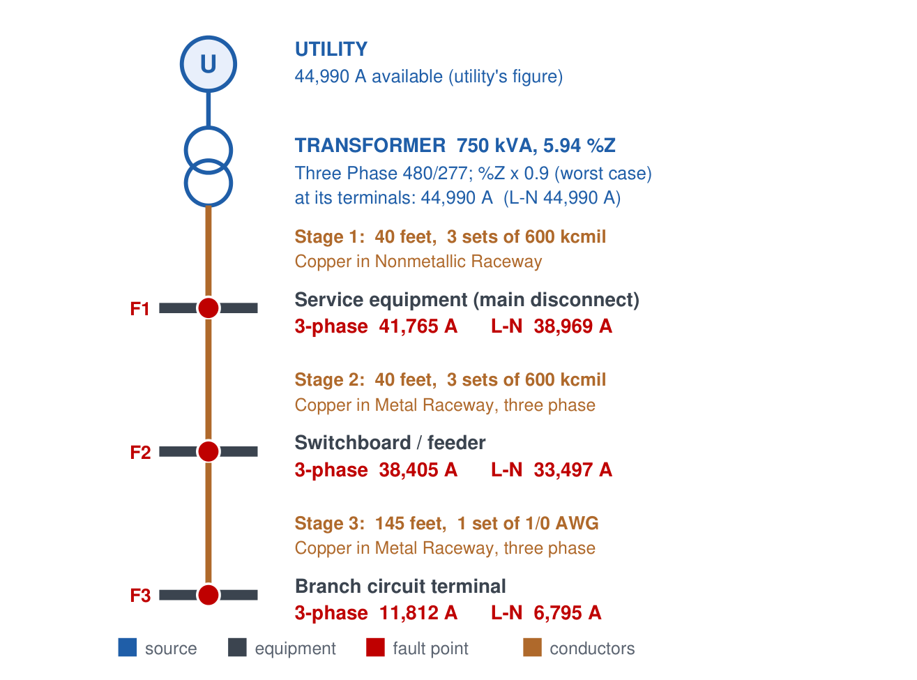
The drawing the Suite made for its own example: a 750 kVA, 5.94 %Z transformer at 480/277 V and three runs of conductor, with the fault current at each point.
The report the Suite wrote for this example: every input, each stage’s point-to-point math, the transformer check, then the drawing.
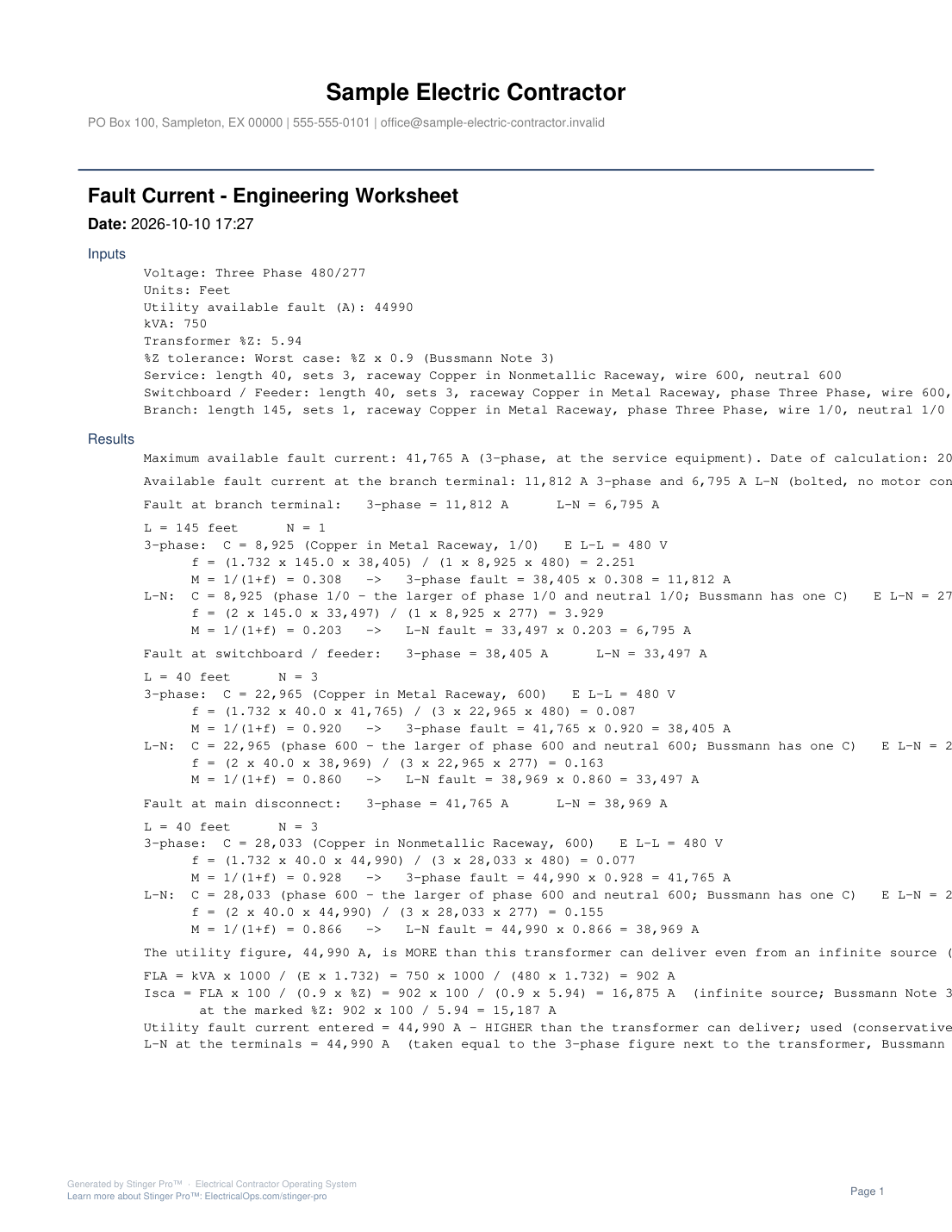
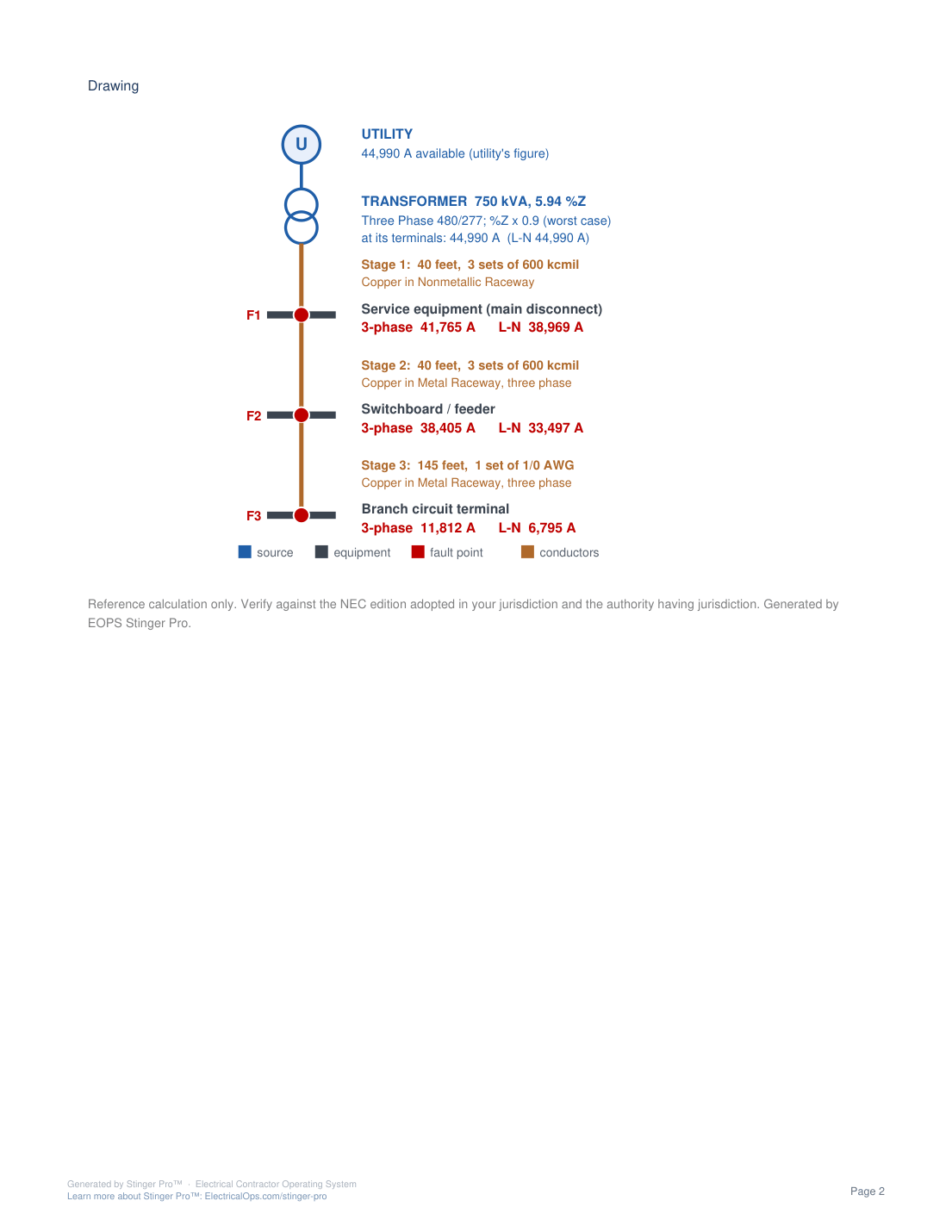
Page 1 lists the inputs and works each fault point, branch first; page 2 is the drawing.
The Suite’s own example, the values the tool opens with, worked out with Calculate All Stages.
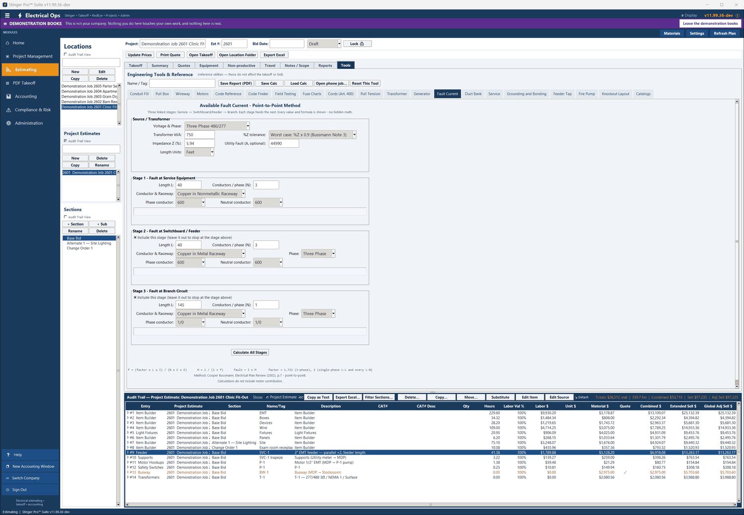
STEP 1 OF 5The example in, before it is worked out: 750 kVA, 5.94 %Z at 480/277 V, a 44,990 A utility fault, and three stages of 40 ft, 40 ft and 145 ft.
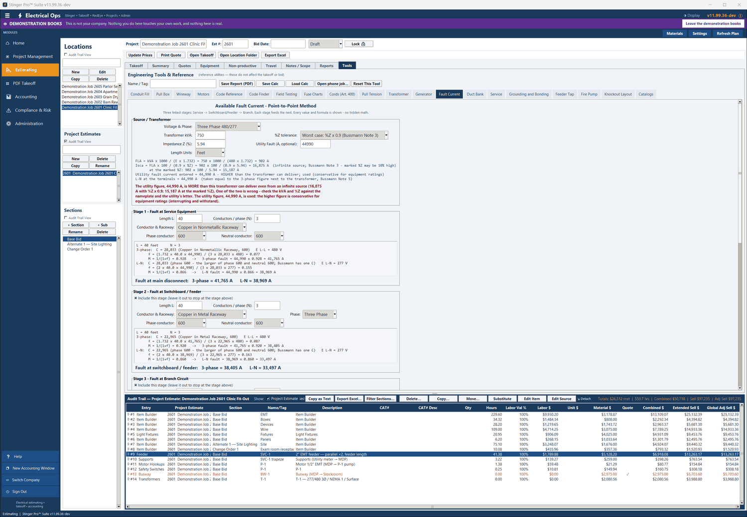
STEP 2 OF 5Worked out: the red warning says the 44,990 A utility figure is more than this transformer can deliver, and uses it as the conservative figure. Stage 1 gives 41,765 A 3-phase at the main disconnect.
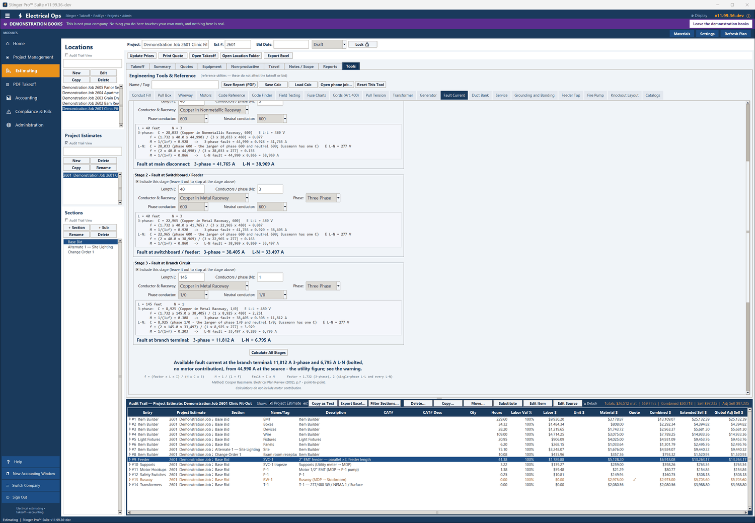
STEP 3 OF 5Stage 2 gives 38,405 A 3-phase at the switchboard; Stage 3 gives 11,812 A 3-phase and 6,795 A L-N at the branch terminal, each with its f and M shown.
![Fault Current in Stinger Pro: The summary and the line for the service disconnect marking: maximum available fault current 41,765 A, with the date of calculation [110.24(A)]. The drawing starts below it.](../../assets/platform/tool-fault-current-03.png)
STEP 4 OF 5The summary and the line for the service disconnect marking: maximum available fault current 41,765 A, with the date of calculation [110.24(A)]. The drawing starts below it.
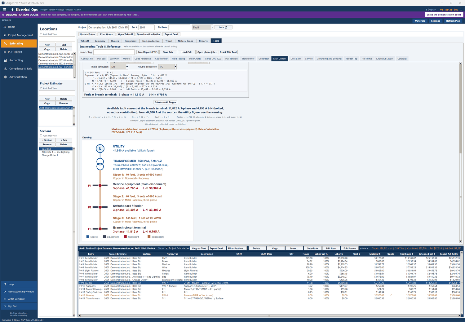
STEP 5 OF 5The drawing: utility, transformer and fault points F1, F2 and F3, with each run’s length and wire and the fault current at each point.