Knockout Layout

Knockout Layout takes the wall size and the conduits with their fittings, and gives back where to punch: each hole center measured from the left and top edges, with the gap that set it and a drawing.

The platform - now showing Knockout Layout

The drawing

The drawing the Suite wrote for a 24 x 12 in wall: each hole to scale, the room its fitting needs drawn around it as an outline, and every center dimensioned from the left edge.
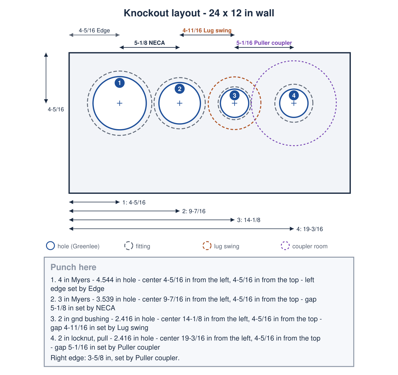
Drawing the program wrote: Four Greenlee holes as solid circles, with dashed outlines around them for the fittings: the Myers hubs on 1 and 2, the grounding bushing on 3 with its lug swing circle, the locknut and bushing on 4 with the puller-coupler room. Centers 4-5/16, 9-7/16, 14-1/8 and 19-3/16 in from the left, all 4-5/16 in from the top; each gap labeled with what set it.
Four Greenlee holes as solid circles, with dashed outlines around them for the fittings: the Myers hubs on 1 and 2, the grounding bushing on 3 with its lug swing circle, the locknut and bushing on 4 with the puller-coupler room. Centers 4-5/16, 9-7/16, 14-1/8 and 19-3/16 in from the left, all 4-5/16 in from the top; each gap labeled with what set it.

The report it writes

The report the Suite wrote for this example: the inputs and where to punch on page 1, the drawing on page 2.
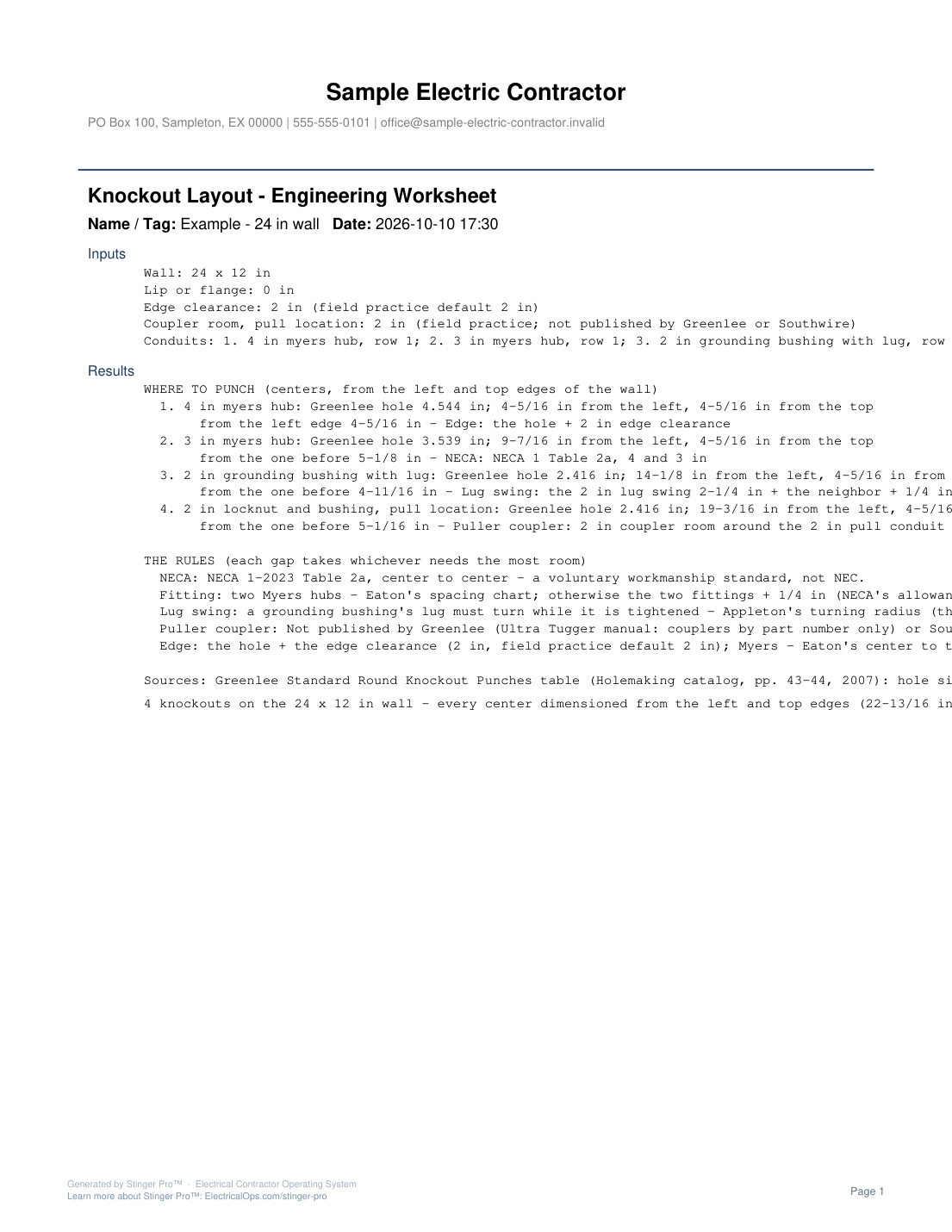
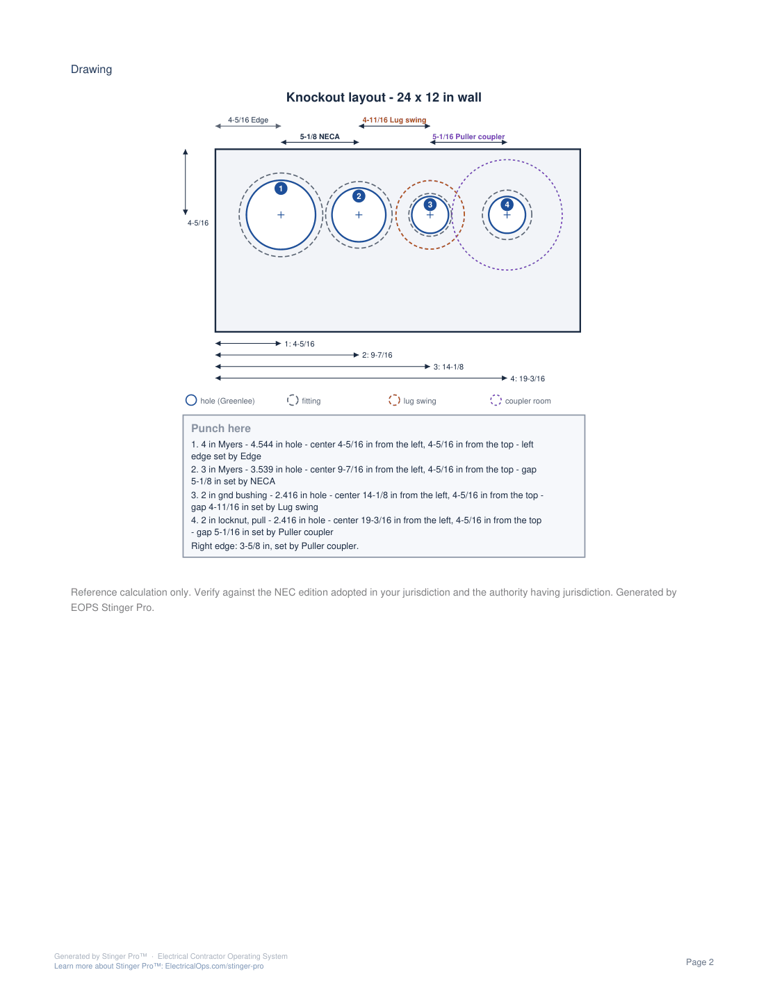
Report page the program wrote: Page 1 of 2
Page 1 of 2
Report page the program wrote: Page 2 of 2
Page 2 of 2

Page 1 lists the wall, the conduits, the hole centers and the rules behind each gap; page 2 is the drawing and the punch list, ending with the 3-5/8 in right edge.

The example, step by step

The phone app's example job, Example - 24 in wall, opened with Open phone job… and worked out by the Suite.
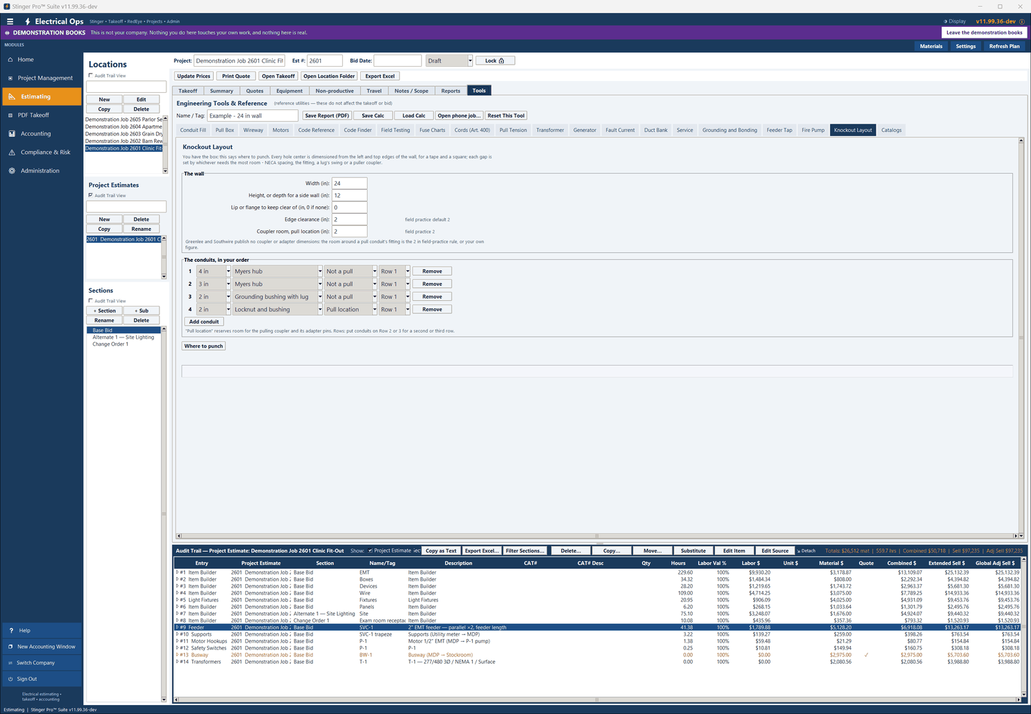
  1. Knockout Layout in Stinger Pro: The example in, before it is worked out: a 24 x 12 in wall, 4 in and 3 in Myers hubs, a 2 in grounding bushing with lug and a 2 in locknut and bushing at the pull location.
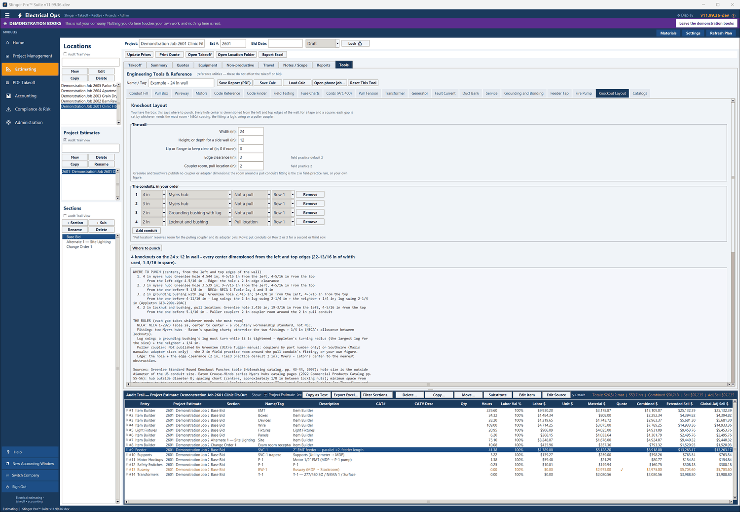
    STEP 1 OF 5The example in, before it is worked out: a 24 x 12 in wall, 4 in and 3 in Myers hubs, a 2 in grounding bushing with lug and a 2 in locknut and bushing at the pull location.

  2. Knockout Layout in Stinger Pro: Where to punch: 4 knockouts, centers 4-5/16, 9-7/16, 14-1/8 and 19-3/16 in from the left, 4-5/16 in from the top, each with the gap that set it.
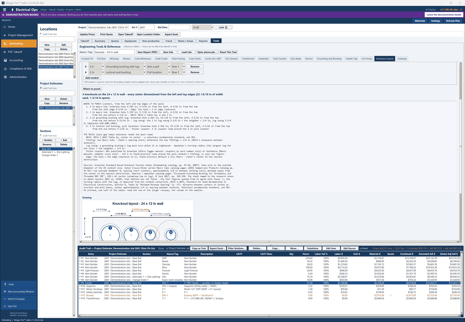
    STEP 2 OF 5Where to punch: 4 knockouts, centers 4-5/16, 9-7/16, 14-1/8 and 19-3/16 in from the left, 4-5/16 in from the top, each with the gap that set it.

  3. Knockout Layout in Stinger Pro: The rules behind each gap and their sources, then the drawing begins: the 24 x 12 in wall with the four holes.
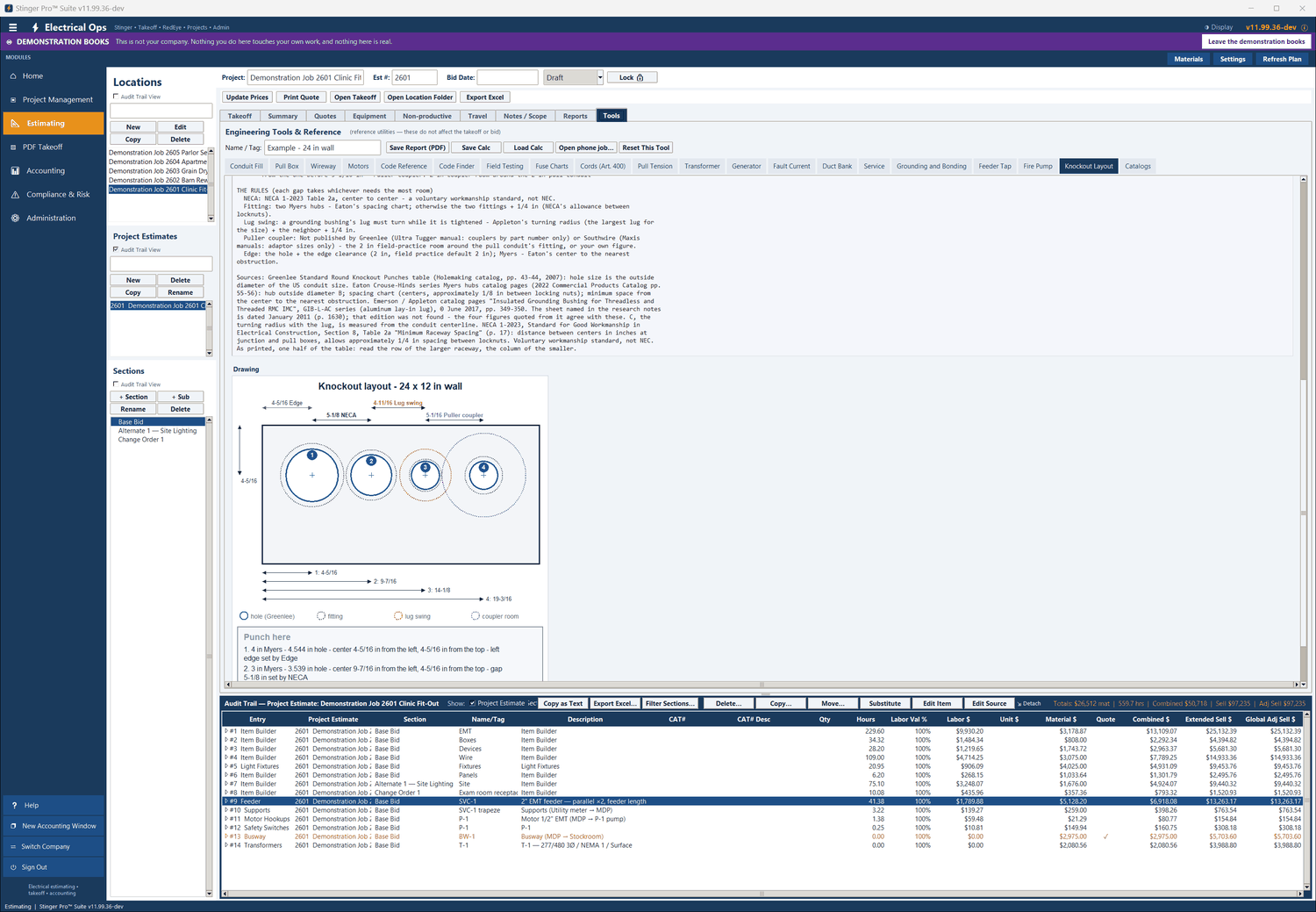
    STEP 3 OF 5The rules behind each gap and their sources, then the drawing begins: the 24 x 12 in wall with the four holes.

  4. Knockout Layout in Stinger Pro: The drawing: each hole with its fitting outline, the lug swing on 3 and the coupler room on 4, dimensioned from the left edge.
    STEP 4 OF 5The drawing: each hole with its fitting outline, the lug swing on 3 and the coupler room on 4, dimensioned from the left edge.

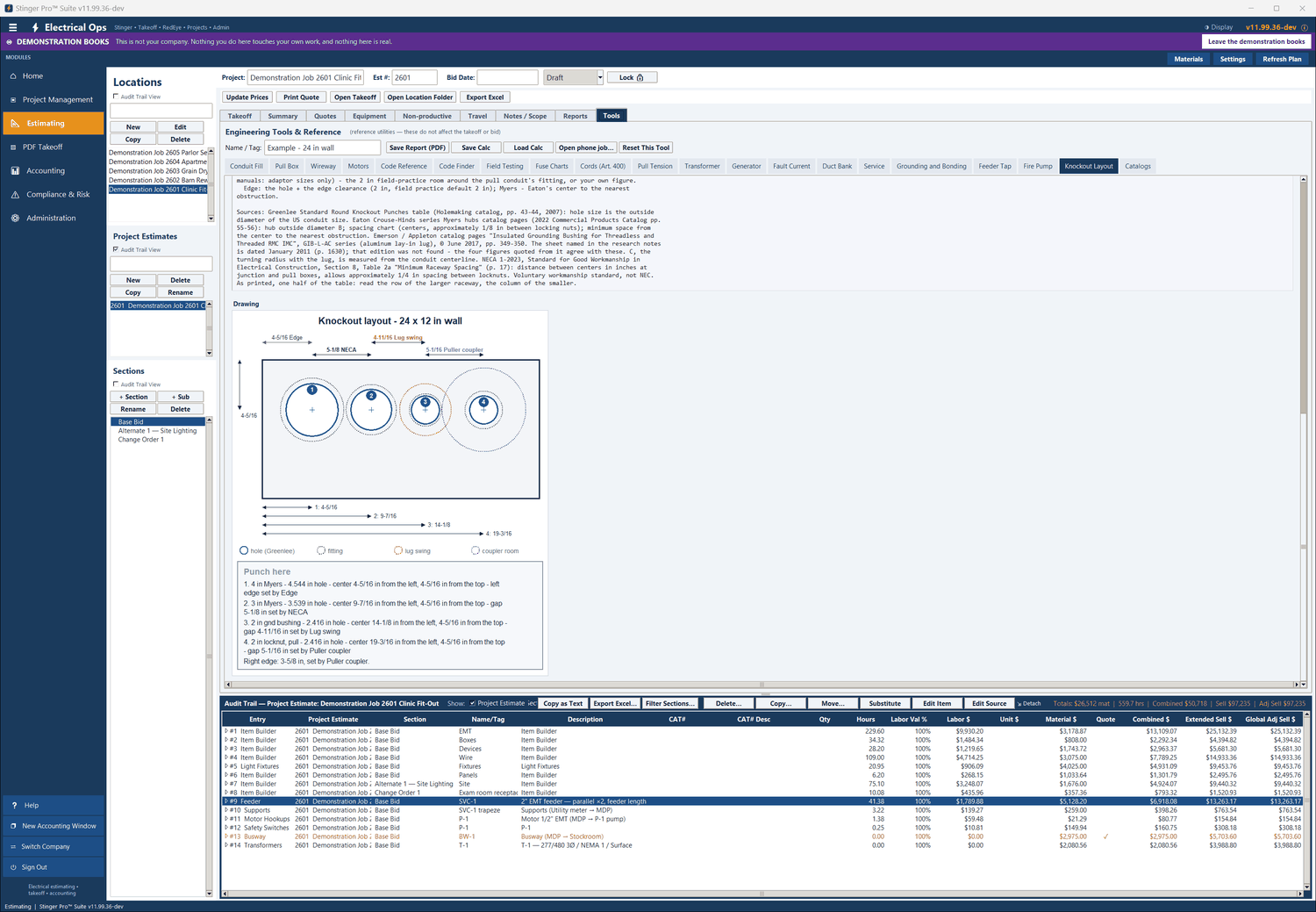
  5. Knockout Layout in Stinger Pro: The whole drawing with the punch list under it: hole size, center and what set each gap; right edge 3-5/8 in.

    STEP 5 OF 5The whole drawing with the punch list under it: hole size, center and what set each gap; right edge 3-5/8 in.